Voltage Divider Simplified: Master Simple Calculations to Control Power with Precision
Voltage Divider Simplified: Master Simple Calculations to Control Power with Precision
A voltage divider is one of the most fundamental yet powerful tools in electrical engineering, enabling precise control of voltage levels from a single power source. By strategically placing resistors in series, this circuit segment splits incoming voltage across components, making it indispensable in sensor circuits, LED dimming, signal conditioning, and calibration. Understanding how to calculate resistor values accurately ensures optimal performance and safety in practical applications.
This guide delivers a clear, step-by-step approach to voltage divider calculations—transforming theory into real-world application with confidence.
At its core, a voltage divider operates on Ohm’s Law and proportional current division. When two or more resistors are connected in series, the voltage across each resistor depends on its resistance relative to the total sum.
The key insight is that voltage divides proportionally to resistance—especially when loaded conditions are minimal. This principle allows engineers and hobbyists alike to generate specific voltages without complex regulators, using only passive components and basic math.
The Anatomy of a Voltage Divider Circuit
A basic voltage divider consists of three primary components: a power supply (Vin), two or more resistors in series (R1, R2, etc.), and a node (Vout) where the output voltage is measured. The formula balancing this circuit is: Vout = Vin × (R2 / (R1 + R2)) This equation reveals a critical dependency: reducing R2 decreases output voltage, while increasing R1 boosts it—highlighting how small resistor variations significantly impact results.The current through the circuit, I = Vin / (R1 + R2), remains constant across all resistors under steady state, assuming ideal passive components. This consistency ensures predictable behavior, essential for reliable design.
When calculating resistor values, maintaining precise ratios is imperative.
Even minor deviations—due to tolerance or temperature shifts—can alter output significantly. For example, a 5% tolerance resistor introduces variability that multiplies when combined with others in series. Designers must therefore select resistors with tight tolerances (1%, 0.5%) or compensate via feedback loops in sensitive applications.
When to Use a Voltage Divider: Real-World Examples
Voltage dividers find use in countless practical scenarios where controlled voltage output is needed without bulky regulators.Common applications include: - **LED dimming circuits**: Adjusting brightness by varying R2 in series with the LED, reducing forward voltage effectively. - **Sensor signal conditioning**: Converting small sensor voltages to usable levels for microcontrollers, minimizing loading effects. - **Calibration references**: Generating stable reference voltages for analog sensors or test equipment.
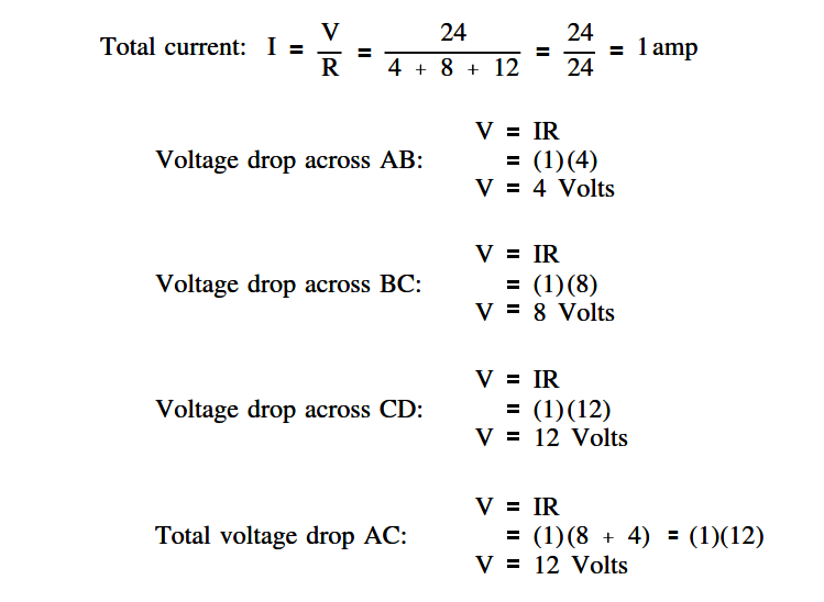
- **Voltage monitoring**: Tracing voltage drops across load resistances to infer current without diverting prime circuit current. In each case, accuracy hinges on selecting resistors with appropriate wattage ratings and matching expected voltage dividers’ load conditions. Overloading resistors risks overheating and failure—thus, current and power budgets must be calculated with care.
Step-by-Step Guide to Voltage Divider Calculations
Performing voltage divider calculations follows a systematic approach, enabling consistent, repeatable results across projects.Step 1: Identify Input Parameters
Define Vin—the source voltage—and determine target Vout. Consider acceptable voltage tolerance and the expected load current, if any.For instance, if Vin = 9 V and Vout must be 3 V, a voltage divider must reduce this ratio. Clarifying the load prevents unnecessary over-sizing resistors.
Step 2: Compute Total Series Resistance
Using Vout = Vin × (R2 / (R1 + R2)), rearrange to solve for total resistance: Rtotal = R1 + R2 = Vin / Vout – 1 With Vin = 9 V, Vout = 3 V, Rtotal = (9 / 3) – 1 = 3 – 1 = 2 Ω.This total resistance must be divided between R1 and R2 according to performance needs.
Step 3: Allocate Resistance Based on Output Voltage
The voltage divider’s heart lies in choosing R1 and R2. Since Vout = Vin × (R2 / Rtotal), set R2 first by desired output, then calculate R1.For example: If targeting 3 V from 9 V, R2 = (Rtotal) × (Vout / Vin) = 2 Ω × (3 / 9) = 2 / 3 Ω ≈ 0.667 Ω However, standard resistor values rarely match 0.667 Ω—common values like 690


Related Post

Microscope Function Body Tube: The Core of Microscopic Precision

Dawn Hasbrouck’s Weight Loss Journey: From Struggle to Sustainable Change
Mike Nicco KGOTV Bio Wiki Age Family Wife Salary and Net Worth

Amaterur Gone Wild: Obsessive Kinetic Energy at Breakneck Velocity