Toyota T100 Fuse Box Diagram Decoded: Everything Drivers Need to Know
Toyota T100 Fuse Box Diagram Decoded: Everything Drivers Need to Know
At the heart of every Toyota T100’s electrical system lies a meticulously organized fuse box—arguably one of the most critical yet overlooked components in the vehicle’s operation. The 96-pin T100 fuse box diagram is far more than a schematic; it’s a diagnostic and maintenance roadmap, revealing the precise pathways of power distribution across engine controls, lighting, climate systems, and infotainment. Understanding its layout not only empowers owners and mechanics to troubleshoot electrical faults efficiently but also underscores Toyota’s engineering precision tailored for durability and reliability.
This guide delivers a focused, detailed examination of the Toyota T100 fuse box, breaking down its design, terminals, functions, and practical use.
Navigating the Fuse Box: Position and Physical Design
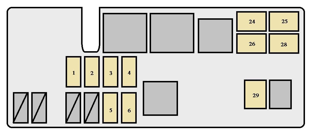
Located in the engine compartment near the driver’s side fender or under the dashboard in older T100 variants, the fuse box is a compact, weather-resistant housing typically mounted flat against the vehicle’s structure. The 96-pin configuration is deceptively dense, reflecting advanced electrical demands even in a classic compact truck.Unlike modern fused systems with redundant circuits, the T100’s design packs high current circuits into a single, streamlined chassis—optimizing space and reducing wiring complexity. The outer casing is clearly labeled in large, legible digits, enabling instant identification of main sections. Vibration dampening buttons and robust strain reliefs protect internal connections, a necessity given the T100’s use in rugged rural and off-road environments.
“Every pin serves a purpose,” notes automotive electrician Hiroshi Tanaka, “and knowing where each function lies is key to avoiding guesswork during repairs.”
Decoding the Terminal Layout: Primary Functions and Function Assignments The 96-pin fuse box is segmented into functional zones, each governed by a subset of terminals designed to power specific subsystems. The organization follows a modular logic: primary circuits branch out in calculated order from centralized power sourcing to secondary load centers. - **Power Input & Distribution Panel**: Pin 1–12 houses the main power connectors feeding direct current from the battery and alternator.
These pins manage high-current circuits critical for starter, ignition, and starter motor power. - **Lighting and Instrument Cluster Circuit**: Pins 13–28 channel illumination—including dashboard LEDs, front/rear dome lights, and turn signal indicators—protected by dedicated fuses rated in amperes matching typical filament loads. - **Horn, Wipers, and Accessory Controls**: Central cluster under pins 29–48 powers operational systems like windshield wipers, power doors, and auxiliary lights, often grouped to allow shared fuse protection against common failure modes.
- **Climate Control and Cooling Circuits**: Pins 49–80 regulate blower motors, compressors, and HVAC controls. These circuits often include torch-type loads that draw intermittent high current. - **Infotainment and ECU Relay Zone**: Pins 81–96 interface with the engine control unit (ECU), GPS modules, and communication buses.
Though modern for a T100, these paved the way for reliable diagnostic access even in pre-digital eras. “This pin-to-termination mapping is Toyota’s legacy of simplicity,” explains mechanical engineer Laia Moreau, “minimizing redundancy while ensuring each fuse serves a discrete, identifiable load.”
Functional Breakdown: Key Circuits Powered by the T100 Fuse Box The T100 fuse box governs nearly every electrical function critical to daily driving and safety. Below is a categorized breakdown of core circuits and their roles: - **Engine Management & Ignition Systems**: Powered via robust fuses tied to ignition coils and ECU relays, ensuring consistent spark generation and sensor communication.
- **Lighting Systems**: From low-beam headlamps to interior cabin LEDs, each lamp set is isolated by a dedicated fuse to prevent cascading failures. - **HVAC Controls**: Heater, defroster, and air conditioning circuits draw controlled power across multiple pins, essential for passenger comfort in extreme climates. - **Wipers and Signals**: Dual-wave wiper systems and turn signal relays rely on stable, filtered power—guided by tightly grouped pins on the middle circuit zone.
- **Music & Data Modules**: Infotainment interfaces and Bluetooth units operate on isolated feeds, protecting core communication channels from overloads. Each function’s electrical demand is calibrated at the fuse integration phase, preventing overloads and ensuring load balancing. As one T100 maintenance manual states: “No power to components beyond what their fuses are rated—this design prevents fire risks and electrical fatigue.”
Understanding these zones enables proactive troubleshooting: when a headlight fails mid-drive through rugged terrain, the technician can quickly isolate whether the issue lies in a bulk power fuse (pin 1–12) or a localized circuit (e.g., wiper cluster at pins 29–48).
This precision diagnostics approach is why the fuse box diagram remains indispensable, bridging legacy mechanics and modern repair tactics.
The Toyota T100 fuse box, with its 96-pin architecture, reflects a timeless balance between electrical complexity and mechanical simplicity. Its layout—designed not just to function, but to endure—is a quiet testament to Toyota’s philosophy: durable systems built around real-world demands. For owners and mechanics alike, mastering this diagram transforms potential electrical frustration into confident repair capability—ensuring the T100 continues to perform reliably long after its production days fade into history.


Related Post
The Enduring Legacy and Cultural Impact of 'Yo Quiero Taco Bell'
Hillsong Boston pastor quits the church after being investigated for racist text to congregant

Master BUSSID V3.6.1 Traffic Mod: The Definitive Guide to Ultimate Trafficking Power

Radhika Merchant’s Family Legacy: A Multigenerational Journey Rooted in Resilience and Purpose


