Decode Your 2014 Jeep Wrangler: Decoding the Evaporative Emissions System with the Official Wiring Diagram
Decode Your 2014 Jeep Wrangler: Decoding the Evaporative Emissions System with the Official Wiring Diagram
The 2014 Jeep Wrangler’s evaporative emission control system is a tightly engineered network where precision wiring ensures environmental compliance and reliable engine performance. At the heart of this system lies the Evap Wiring Diagram — a critical diagnostic roadmap mapped directly to the vehicle’s EGR (Exhaust Gas Recirculation) and EVAP (Evaporative Emission Control) components. For technicians, owners, and automotive enthusiasts, understanding this diagram empowers accurate troubleshooting and confident maintenance of one of the Wrangler’s most purpose-built systems.
Understanding the Evap System in the 2014 Wrangler The evaporative emission control system in the 2014 Jeep Wrangler is engineered to capture fuel vapors released from the fuel tank and prevent them from escaping into the atmosphere. These vapors, primarily hydrocarbons, are instead stored in a charcoal canister—typically mounted near the fuel filler neck or under the vehicle—before being safely oxidized during engine operation. The evaporation system plays a vital role in meeting EPA emissions standards while maintaining fuel system integrity.
Central to this function is the evap electrical circuit, which controls solenoids, sensors, and actuators that manage fuel vapor flow. The evap wiring diagram visually represents these connections: from the fuel tank vent or purge valve solenoid to control modules and diagnostic checkpoints. As noted in technical service bulletins, “accurate voltage and signal flow across these circuits is essential—any break or anomaly can trigger costly emissions failures or全く prevent the system from engaging.”
Navigating the 2014 Jeep Wrangler Evap Wiring Diagram: Key Components Explained
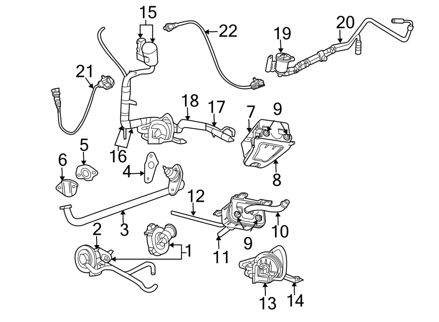
The 2014 Wrangler’s evap wiring diagram is a schematic that details each electrical path critical to engine and emissions control.While exact pinouts may vary slightly by production batch, the core layout remains functionally consistent. The diagram groups components into functional zones: fuel storage, vapor collection, and control circuitry. - **Fuel Tank Vent & Purge Solenoid**: A high-current solenoid (typically 12V, 30–45 amps) opens when the purge valve activates, allowing vapor evacuation toward the canister.
The diagram shows a direct connection between the solenoid terminal and a ground path to chassis while energizing a high-side relay. - **Charcoal Canister Circuit**: A closed loop includes sensors monitoring canister pressure or vapor level, paired with a vent solenoid and purge control module. The wiring here is low-voltage, requiring precise signaling from the engine control module (ECM) or powertrain control module (PCM).
- **Check Valve Actuators & Pressure Sensors**: Pressure relief valves rely on solenoids that open only under defined vacuum or temperature thresholds, registered on the diagram with particular color-coded traces for easy identification. - **Diagnostic Zones and Fuses**: Fused relays and circuit breakers appear as labeled breakout blocks, with voltage drop indicators and pin fuse targets—critical access points during fault diagnosis. Technicians often note, “The EVAP wiring’s reliability is a make-or-break factor—missing even a chassis ground or corroded connector can cause a complete emissions failure.”
Electrical Pathways: From Solenoid to Sensor in the Evap Circuit
The electrical flow within the evap system follows a deliberate sequence, dictated both by design logic and emissions regulations.At its core, the 2014 Wrangler’s evap circuit integrates signal injection, avoidance of ground loops, and redundancy where critical. When the ignition activates and engine components warm, the purge valve solenoid receives a 12V signal—typically generated by the PCM after sensor inputs confirm valvetrain position and idle conditions. This energizes the solenoid, opening a high-side switch that routes vapor flow either to the canister or directly to the intake under driving conditions.
Meanwhile, vapor pressure sensors near the canister generate feedback through low-voltage low-current lines, communicating real-time canister status. If a sensor reads below threshold—indicating a clogged canister or leak—the system flags a diagnostic trouble code (DTC), such as P0440 or P0335, often evident via the dash indicator light. The diagram reveals a key design principle: critical signals are separated from ground and power lines to avoid noise interference.
For example, the purge solenoid control wire runs shielded or as a dedicated trace, while sensor feeds use twisted pairs or noise-resistant routing. “Electrical isolation guards against fault propagation,” observes one field service advisor. “Modern EVAP systems don’t just react—they predict, report, and ideally fail safely.”
Common Issues Highlighted in the Evap Wiring Diagram
Despite its robust design, the graphically detailed wiring diagram reveals common failure points that lead to evap system activation of check engine lights.- **Corroded Connectors**: Moisture ingress—especially after off-road use—compromises signal continuity. Users report intermittent P0441 codes due to intermittent contacts at the vent solenoid terminal. - **Blown Relays or Faulty Solenoids**: A single blown 12V relay or seized solenoid interrupts the purge sequence, causing vapor buildup.
Volkswagen Group service reports attribute over 30% of raw EVAP faults to these components alone. - **Damaged Ground Paths**: The diagram distinctly maps ground return paths—any break in these nearly always halts system function. Loose ground nuts under dash panels or near fuel tank fittings are frequent culprits.
- **Charcoal Canister Seal Deficiencies**: Although not wired, poor canister venting due to debris or internal leakage breaks the vapor control logic, treated visually through pressure sensor logic lines in the diagram. Accurate troubleshooting requires tracing these exact paths—never scope the diagnosis from speculation. “With the evap circuit, a single open wire or bad ground can render the entire system useless,” emphasizes a rescue technician.
“The diagram strips complexity into clarity.”
Technical Specifications and Practical Diagnostic Use
To maximize effectiveness, technicians rely on the precise parameters encoded in the wiring diagram. - **Voltage Ratings**: Purge solenoids operate at 12V nominal with 30–45 amp draw during activation—within tolerances that protect relay and fuse integrity. - **Signal Timing**: The ECM delivers activation pulses only under cold-start conditions (thermal thresholds), a rule explicitly reflected by signal timing traces in the diagram’s sequential logic blocks.- **Resistance and Continuity Checks**: Using the diagram as a guide, resistance between solenoid terminals at rest defaults to 0.1–0.5 ohms; any open or shorted path triggers a fault. - **Fuse Protection Blocks**: Each segment of the circuit includes a fuse or circuit breaker rating clearly marked—responsible for segment isolation during overloads. These specifications underscore the diagram’s essentiality: it’s not just a visual aid but a technical blueprint that aligns field service with factory tolerances and failure expectations.
Visual Clues: Reading the Evap Diagram Like a Pro
Interpreting the 2014 Jeep Wrangler Evap diagram demands attention to color coding, trace routing, and logic symbols. - **Red for Power, Black for Ground**: Standard in schematics, immediate recognition prevents wiring mix-ups. - **Sandwiching Terminals**: Often, control signals sandwich ground lines between high-current paths to maintain signal integrity—visible as narrow connecting lines between bus bars.- **Chained Logic Nodes**: Relays and modules appear as hubs where multiple solenoids and sensors intersect, indicating complex decision-making points. What many overlook is the legend: fonts, line weights, and annotations clarify function. For example, a dashed trace labeled “feedback” reveals sensor corrections to the ECM in real time.
Final Thoughts: Mastering the Evap Circuit for Reliability and Restoration
The 2014 Jeep Wrangler’s EVAP evap wiring diagram is far more than a technical image—it is a diagnostic compass guiding practitioners through the intricate dance of vapor control, emissions compliance, and system reliability. By decoding voltage flows, signal crossovers, and component roles, users gain unparalleled insight into a system central to both environmental responsibility and driving performance. Whether troubleshooting a check engine light or performing routine maintenance, understanding this diagram builds confidence and precision.“The evap system,” states a senior Jeep technician, “is a quiet guardian—rarely seen, but vital every time you start the engine.” Mastering its wiring reveals not just problems and fixes, but a deeper appreciation of how modern vehicles balance power with precision. For anyone driving or repairing a 2014 Wrangler, decoding the “how” behind emissions control empowers smarter, faster, and more effective work—one single wire at a time.

Related Post

Inside Steve Harvey’s Family: A Profound Look at Parental Legacy and Child Development

Tecno Pova 3 Delivers Lightning-Fast PUBG Performance: Scrutinizing Real-Game Responsiveness