Deciphering Hydraulic System Diagrams: Master the Language of Fluid Power with Precision
Deciphering Hydraulic System Diagrams: Master the Language of Fluid Power with Precision
Hydraulic systems power some of the most vital machinery across industries—construction equipment, aircraft controls, factory automation, and emergency response vehicles. Yet, for engineers, technicians, and operators, interpreting hydraulic system diagrams remains a cornerstone skill essential to maintenance, troubleshooting, and design. Deciphering hydraulic system diagrams is more than reading schematics—it’s unlocking the logic of fluid dynamics, pressure management, and component interconnections.
This comprehensive guide reveals how to systematically interpret these diagrams, decode symbols and flow paths, and apply that knowledge effectively in real-world settings.
Hydraulic system diagrams serve as visual blueprints of complex interactions between pumps, valves, actuators, reservoirs, and hoses. These diagrams translate physical fluid circuits into standardized schematic language, allowing professionals to visualize pressure distribution, flow direction, and functional relationships.
Despite decades of standardization, the graphic conventions can still appear dense and unintuitive to newcomers—especially when cross-referenced with technical datasheets or operational manuals. Understanding the standard symbols, labeling conventions, and circuit topology is therefore not just helpful; it’s critical for safe and efficient hydraulic system management.
Decoding the Language of Hydraulic Symbols
At the heart of every hydraulic diagram are universal symbols that represent physical components.Recognizing these symbols is the first step to meaningful interpretation. - **Pumps and Motores:** Typically shown as a circle or elongated oval with an arrow inside—indicating fluid flow direction. Positive displacement pumps, such as gear, vane, or piston types, differ in symbol detail, often including dotted outlines or shading to reflect internal mechanics.
- **Valves:** Valves control flow and pressure, and in diagrams, they appear as a mix of circles, angles, and chambers. Directional control valves feature labeled ports (inlet, outlets) and specific internal flow paths, sometimes with solenoid references. Relief and pressure valves often sport simplistic but distinctive shapes with pressures denoted in bars or psi near terminals.
- **Actuators and Cylinders:** Double-acting cylinders are depicted as cylinders with rod and cap ends; single-acting units show only the extended piston side. Fluid schematics near cylinders indicate inlet and exhaust ports, often color-coded or labeled with flow arrows. - **Reservoirs:** Large rectangular boxes with internal fins denote fluid storage, often annotated with volume or capacity.
“The first hurdle for technicians is associating each symbol with its real-world counterpart,” explains Dr. Elena Rodriguez, senior hydraulic systems engineer at DevTech Hydraulics. “Standard symbols, as defined by ISO 4413 and SAE J1756, provide a common language—but subtle variations in schematic representation still require context.”
Beyond symbols, understanding how components connect is vital.
Flow lines—often depicted in flowing arrows—indicate direction and velocity of hydraulic fluid, revealing loop configurations, pressure zones, and return paths. Solid lines usually represent direct connections, while dashed lines suggest recirculation or feedback loops. Position indicators on valves and proportional regulators further specify dynamic behavior, such as stepped or continuous adjustments under variable load.
Flow of Fluid: Understanding Circuit Pathways and Pressure Systems
Hydraulic diagrams illustrate three primary fluid pathways: closed loops, series circuits, and parallel branching. Each configuration performs distinct functional roles: - **Closed-Loop Circuits** maintain continuous fluid flow through a single path, typically powering actuators in controlled, self-contained sequences. - **Series Circuits** route fluid sequentially through multiple components—common in pressure boosting or multi-stage pump systems.- **Parallel Circuits** branch off shared flow to enable redundant or simultaneous actuation, crucial in handling diverse forces across machines. Pressure zones are often marked by labeled numbers or proportional values (e.g., 150 bar, 300 psi), helping technicians verify operating parameters and detect anomalies. Return lines—often depicted with opposing arrow directions—show fluid redirected from actuators back to reservoirs or reservoirs, ensuring system efficiency and preventing pressure loss.
“Flow patterns aren’t just about connectivity,” notes Marcus Finch, hydraulic design specialist at StabilTech Engineering. “Diagrams encode the intent behind fluid routing—whether to stabilize operation, isolate faults, or balance loads. Interpreting these intentions reveals why certain pathways exist and where bottlenecks might form.”
Another key element is labeling: ports, valves, and component designations are annotated with letters, number sequences, and function codes.
These labels serve dual purposes—identifying real-world parts and linking schematics to maintenance logs, part numbers, or calibration data. Precision in reading these labels avoids misdiagnosis and reduces repair time significantly.
Labeling, Codes, and Industry Standards: Ensuring Consistency Across Schematics
Hydraulic schematics follow strict coding standards—ISO 4413 and ISO 14126 being the most widely adopted—ensuring consistency whether illustrated in a Microsoft Visio drawing or a field technician’s handheld tablet.These standards define symbol shapes, line types, label formats, and component annotations, making diagrams instantly interpretable across teams and regions. Each component carries identifiers: pumps are labeled “P,” valves “V,” and actuators “A,” assisting rapid equation-scanning. For example, a diagram showing a relief valve with “EV-10” and “P-07” directs attention precisely to its function and integration point.
Pressure ratings are typically displayed within symbols (e.g., “150 bar”) or in footnotes, allowing quick assessment of component limitations. IGN: Systems designed to comply with ISO standards not only reduce ambiguity but also streamline global operations—critical for multinational engineering firms and field service teams collaborating across time zones and languages.
Reliability in hydraulic interpretation hinges on recognizing these codes and associates.
Without them, even accurate symbol recognition becomes insufficient—contextual coding closes the loop between schematic and system reality.
Practical Techniques for Mastering Diagram Complexity
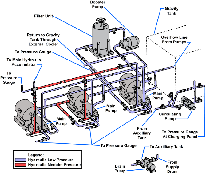
Deciphering complex hydraulic diagrams demands both foundational knowledge and strategic approaches. Experienced technicians rely on proven techniques to unpack layered circuits: - **Start with the Core Circuit:** Identify the primary power source, main pump, and main actuators first.Map their interconnection before analyzing auxiliary components. - **Trace Flow Sequentially:** Follow fluid paths from input to output, noting direction, pressure drops, and switching valves. This reveals operating logic and identifies high-traffic routes prone to wear.
- **Highlight Control Logic:** For circuits integrating solenoids or electronic controls, note logic gates, timing sequences, and proportional outputs—key in CNC hydraulic presses and automated machinery. - **Cross-Reference with Documentation:** Match diagram connections to as-built drawings, maintenance manuals
![[DIAGRAM] Fenner Fluid Power Wiring Diagrams - MYDIAGRAM.ONLINE](https://instrumentationtools.com/wp-content/uploads/2018/10/Pictorial-Fluid-Power-Diagram.png)

Related Post

Shah Abbas and the World History Giant: Architect of a Global Ottoman-Persian Renaissance

Katy Solt Spectrum News Bio Wiki Age & Highlighting Her Marital Journey: Age, Husband, and Public Profile


